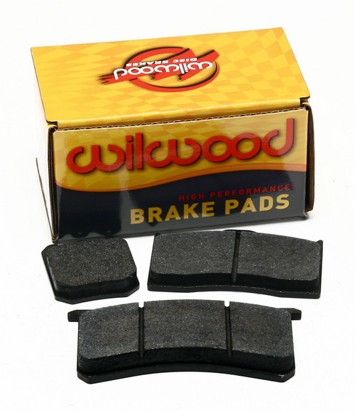
Wilwood PN 260-10922
SPECIFICATIONS:
Adjustment Style:Knob
Inlet Quantity:One
Inlet Attachment:Female threads
Inlet Size:3/8-24 in. inverted flare
Outlet Quantity:One
Outlet Attachment:Female threads
Outlet Size:3/8-24 in. inverted flare
Minimum psi:100 psi
Maximum psi:1,000 psi
Pressure Reduction (%):57 percent
Proportioning Valve Finish:Clear anodized
Proportioning Valve Material:Aluminum
Sold individually.
WARNING:
IT IS THE RESPONSIBILITY OF THE PERSON INSTALLING ANY BRAKE COMPONENT OR KIT
TO DETERMINE THE SUITABILITY OF THE COMPONENT OR KIT FOR THAT PARTICULAR
APPLICATION. IF YOU ARE NOT SURE HOW TO SAFELY USE THIS BRAKE COMPONENT OR
KIT, YOU SHOULD NOT INSTALL OR USE IT. DO NOT ASSUME ANYTHING. IMPROPERLY
INSTALLED OR MAINTAINED BRAKES ARE DANGEROUS. IF YOU ARE NOT SURE, GET HELP
OR RETURN THE PRODUCT. YOU MAY OBTAIN ADDITIONAL INFORMATION AND TECHNICAL
SUPPORT BY CALLING WILWOOD AT (805) 388-1188, OR VISIT THIER WEB SITE AT
WWW.WILWOOD.COM. USE OF WILWOOD TECHNICAL SUPPORT DOES NOT GUARANTEE
PROPER INSTALLATION. YOU, OR THE PERSON WHO DOES THE INSTALLATION MUST KNOW
HOW TO PROPERLY USE THIS PRODUCT. IT IS NOT POSSIBLE OVER THE PHONE TO
UNDERSTAND OR FORESEE ALL THE ISSUES THAT MIGHT ARISE IN YOUR INSTALLATION.
RACING EQUIPMENT AND BRAKES MUST BE MAINTAINED AND SHOULD BE CHECKED
REGULARLY FOR FATIGUE, DAMAGE, AND WEAR.
INSTALLATION & ADJUSTMENTS
Proportioning valves are normally installed in the rear fluid line to
prevent the rear wheels from locking before the front wheels, or to give a driver the ability to make fine
adjustments in front to rear bias percentage on the track to compensate for tire wear, fuel load burn-off, or
changing track conditions. It is generally not recommended to attempt to reduce front wheel braking capacity.
Use only the two .25" body holes to secure the valve to a mount. Do not attempt to remove the adjuster knob
or valve body end cap to facilitate thru-panel mounting.
The two ports are 3/8-24 inverted flare seats to adapt double flared hard brake lines directly to the valve.
Connect the "IN" port to the pressure line coming from the master cylinder. Connect the line going to the
calipers to the "OUT" port.
The adjusting knob is marked with an arrow indicating the direction required to decrease line pressure to the
calipers. The knob rotated all the way out (counter-clockwise) will provide a maximum pressure reduction of
57%. Rotating the knob in (clockwise) will incrementally increase line prressure, up to full pressure. If the
range of adjustment in the valve is not sufficient to properly balance the vehicle’s bias, changes to other
components within the system may be necessary.
TESTING THE SYSTEM - Do not attempt to operate the vehicle until the system has been fully tested under
controlled conditions in a safe location. After the system has been bled, checked for leaks, and the proper
pedal resistance and travel have been determined, make a series of low speed stops, then gradually progress
to normal operating speeds.
WARNING - Adjustable proportioning valves are designed for tuning and balancing custom brake systems on
performance, racing, and other types of special purpose vehicles. They are not designed as direct
replacements for any OEM application.
NOTE: This proportioning valve will require brake line work to install. It is not a direct replacement for any stock proportioning valve.


